
Please read the instruction manual carefully before installing and using this product
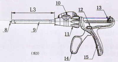
The type and basic dimensions of the endoscope linear cutting stapler are shown in Figure 3.
8. Transmission rod 9. Casing 10. Steering wrench 11. Steering handle 12. Firing button 13. Push handle 14. Movable handle 15. Fixed handle
Figure 3 :Schematic diagram of the structure of the endoscopic linear cutting stapler
Contraindications of endoscopic linear cutter stapler
1. Severe mucosal edema;
2. It is strictly forbidden to use this device on liver or spleen tissue. Due to the compression characteristics of such tissues, the closure of the device may have a destructive effect;
3. It cannot be used in parts where hemostasis cannot be observed;
4. Gray components and brown components cannot be used for tissues whose thickness is less than 0.75mm after compression, or tissues that cannot be properly compressed to a thickness of 1.0mm or tissues on the aorta;
5. White components cannot be used for tissues whose thickness is less than 1.0mm after compression, or tissues that cannot be compressed to a thickness of 1.5mm or tissues on the aorta;
6. The blue component and the purple component cannot be used for tissues whose thickness is less than 1.5m after compression, or tissues that cannot be properly compressed to 2.0m thickness or tissues on the aorta.
7. Black components cannot be used for tissues whose thickness is less than 1.75mm after compression, or tissues that cannot be properly compressed to a thickness of 2.25m or tissues on the aorta;
8. Green components cannot be used for tissues whose thickness is less than 2.0mm after compression, or tissues that cannot be compressed to a thickness of 2.5mm or tissues on the aorta.
Installation of endoscopic linear cutter stapler:
How to use S-cutting components:
1. Select the stapler body and corresponding components according to the different scope of application during the operation.
2. Install components
Install the components on the body. Align the socket of the component with the socket on the top of the body (the indication mark on the component and the indication mark on the body must be aligned), and then insert it to the end. (Figure 4) Then rotate the component counterclockwise by 45 degrees, and the component will be locked. (Figure 5)
Notice:
1) The component is loaded in an open state and cannot be closed;
2) Do not remove the protective cover of the module before the module is installed;
3) Ensure that the push handle on the body is fully retracted. (Image 6)
After the components are installed, firmly grasp the movable handle once to close the jaws, and then pull the push handle back to fully open the jaws.
3. Unloading components
Remove the component from the body.
Pull the unlocking button back, turn the assembly 45 degrees clockwise, and pull the body forward. (Picture 7)
Post time: Oct-27-2022


