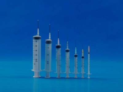
Inspection Procedures for Disposable Syringes for Drug Dispensing
2.1 Sterility test:
Preparation of test solution:
Take 6 dispenser samples, suck 0.9% sodium chloride injection into the dispensing device in the sterile room to the total calibration volume, pull back the core rod, and make the piston shake 5 times slightly above the liquid level. The test solution should be stored for no more than 2 hours.
Sterility test shall be carried out with the inoculation amount of 1.0ml per tube and the culture medium of 15ml. Sterility test shall be carried out after 14 days of culture.
2.2 Bacterial endotoxin test:
See Appendix II for test method
3. Physical performance
3.1 Appearance
a. Under the illumination of 300LX-700LX, the dispenser should be clean and free of particles and foreign matters;
b. Dispenser shall be free from burrs, burrs, plastic flow defects, etc;
c. The jacket shall be transparent enough to clearly see the reference line;
d. There shall be no obvious lubricant accumulation on the inner surface.
3.2 Dimensions
It shall comply with the provisions of 5.2.2 in the standard, and the additional dimensions shall be distinguished from the scale of the standard volume, meeting the requirements of a, b, c and d.
3.2 Number of ruler
Mark the scale capacity line according to the division value specified in Table 1 of the standard; The printing position of the zero position line shall be tangent to the inner edge line of the jacket bottom cover. When the core rod is completely pushed into the jacket bottom cover, the zero position line shall coincide with the reference line on the piston, and the error must be within 1/4 of the minimum indexing interval; The capacity line shall be separated from the zero position line to the total scale capacity line along the long axis of the jacket; One end of all equal length dividing capacity lines in the vertical position of the dispensing device shall be aligned with each other in the vertical direction; The secondary indexing shall be one half of the primary indexing capacity line.
3.3 Total scale length of nominal capacity line
The total length of the ruler shall be in accordance with Table 1 of the standard
3.4 Ruler position
Measurement figures: the font shall be straight; The position shall intersect with the extension line at the end of the main indexing capacity line, but shall not contact; The measurement figures shall be arranged from the "zero" position line at the back cover of the jacket, and "zero can be omitted";
Ruler printing: The offset type shall be printed on the opposite side of the cone head. The middle head type shall be printed on either side of the sleeve crimping short shaft; The printing shall be complete, with clear handwriting and lines and uniform thickness.

3.5 Coat
The length of the maximum usable capacity of the jacket shall be at least 10% longer than the nominal capacity.
The opening of the outer sleeve of the dispensing device shall be crimped to ensure that the dispensing device cannot be rotated 180 ° when it is arbitrarily placed on the plane with an angle of 10 ° to the horizontal
3.6 Hand spacing
When the core rod is completely pushed into the outer casing seal, make the reference line of the piston coincide with the zero line. The preferred minimum length from the inside of the crimp to the outside of the handle should meet the spacing specified in the following table.
3.7 Piston
The rubber piston shall be free of rubber threads, rubber chips, foreign impurities and frost spraying, and shall comply with YY/T0243; The piston is matched with the jacket, and the core rod will not move due to its own weight after the dispenser is filled with water.
3.8 Taper head
a. The diameter of cone head hole shall not be less than 1.2mm.
b. The outer cone joint of cone head shall be in accordance with GB/T1962.1 or GB/T1962.2.
C. Middle end dispenser: the cone head shall be located in the center of the bottom end of the jacket and on the same axis with the jacket.
D. Eccentric dispensing device: the cone head deviates from the center at the bottom end of the outer casing and should be located on the centerline of the side of the short axis of the outer casing crimping, and the distance between the cone head axis and the nearest point on the inner wall surface of the outer casing should not be more than 4.5mm.
3.9. Body tightness
3.9.1 Draw the dispenser into water with nominal capacity, seal the cone head hole, and apply a force of 30 to the core rod as specified in Table 1 to ensure no leakage.
3.9.2 Adjust the water to no less than 25% of the nominal capacity, make the cone head upward, and draw back the piston to make the reference line coincide with the nominal capacity line. When the suction air from the cone head hole reaches 88 kPa negative pressure, maintain it for 60+5s, and there is no air leakage at the position where the outer sleeve contacts the piston, and it shall not be separated.
Post time: Sep-28-2022


